⚙️ Power Up Your Projects with Precision!
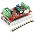
The RioRand 350W 6-60V PWM DC Brushless Electric Motor Speed Controller is a high-performance driver designed for three-phase brushless motors with Hall sensors. It features a wide voltage range, robust power output, and advanced control capabilities, making it ideal for both professional and DIY applications. With built-in safety measures and a user-friendly design, this controller is perfect for those looking to elevate their motor control experience.


| Material Type | Copper |
| Voltage | 60 Volts |
| Horsepower | 350 Watts |
| Speed | 6 Volts (DC) |
A**R
Works fine with Arduino (Sample code below)
It took a little bit to figure out the wiring. I was able to crack open my 36V hub motor and clearly read the labels but they didn't correspond to the motor controller.I did have to short the Jumper.As far as getting it to work with an Arduino:- I used an Arduino Nano to test.- Used the PWM.h library to set the pin frequency to 20khz- Connected one Arduino pin to "DIR" line and set pin to "HIGH" or "LOW" for Fwd and Rev.- Used the "G" (Ground), "P" (PWM) and V (5V) connections located by the Jumper to connect to the Arduino. This powered the Arduino as well.Sample code (I am not the best programmer but it worked):// Sample Code for one motor#include <PWM.h> //Used to set pwm frequency to 20khzint Direction = 10; // pin connected to the "Dir"int Motor = 9; // pin connected to "P" PWM Signal input"int32_t frequency = 20000; //frequency (in Hz) 20khzvoid setup() {//initialize all timers except for 0, to save time keeping functionsInitTimersSafe();//sets the frequency for the specified pinbool success = SetPinFrequencySafe(Motor, frequency);//if the pin frequency was set successfully, turn pin 13 on (Built in LED)if (success) {pinMode(13, OUTPUT);digitalWrite(13, HIGH);}pinMode(Direction, OUTPUT);}void loop() {digitalWrite(Direction, HIGH); //Set direction clockwisepwmWrite(Motor, 200); //Spin motor between 0-255, in this case 200delay(5000); // for 5 secondspwmWrite(Motor, 0); //Spind motor downdelay(3000); //for 3 secondsdigitalWrite(Direction, LOW); //Set direction counter clockwisepwmWrite(Motor, 200); //Spin motordelay(5000); // for 5 secondspwmWrite(Motor, 0); //Spin motor downdelay(3000); //for 3 seconds}
J**N
PWM pin solved plus pulse for RPM!!
I have the Hall Sensor version. Spent a lot of time finding the correct phase wiring order. But hardest part was getting the PWM to work.First:The jumper is needed, mine was just solder pads so I soldered pins and put jumper. Refer to the picture linked to this product.Second:The tiny 5 pin pads on the same side as the jumper, the Vcc and Gnd are same as the screw terminal (for pot). You will need to solder a pin to the one marked "P". I used the screw terminals for Vcc and Gnd (caution, they are 5v). PWM connection to the "P" pin and you are good to go.I am using SEEED nRF52840 and it is 3.3v but it has a 5v pin, I power it off the motor driver and the PWM works great with only 3.3v output from digital pin. I'm running at 20k PWM freq.Only 4 stars as no documentation and a lot of trial and error to run down the wiring.Ok, I changed to 5 stars as I found that the middle pin on the side with my last picture with clip is "PULSE" output. I used interrupt to count the pulses and then divided by 12 to get one revolution.
B**M
It does work, if wired correctly, but setup may not be easy
I bought two, to control two motors.At first, control was terrible. Very jerky, pulling high current. After investigation, swapping the motor lines made it work correctly. But, the motors being driven had colour coded wires and labels that were connected to match the controller inputs - its 50/50 whether its the motor or the controller that has the logic wrong.But, end result was that I could control the motors, from a power supply as the source.I took out the other controller and changed to use a battery source for power, there was a large spark at the connection. Surprised, I flinched away, and then connected again almost straight away. Not sure what went wrong there - the plug was polarised, so I couldnt have reversed it, but the controller stopped working after that. Something has blown on the 5V logic, the 'on' led wasnt lighting up.(though it did briefly). I dont really know what happened, but I dont know for sure that I didnt cause that. I ended up ordering another one to replace it, so fingers crossed.I installed a proper switch with the remaining controller and was able to get it powered off a battery (42V) without sparks or failures.So, overall, yes, they work, but be careful of wiring labels and potential inrush current problems.
F**.
Reverse/Forward doesn't work.
The motor is spinning just fine; however, you can't change the spinning direction. The motor is humming and doesn't spin when you activate the DIR terminal by shorting it with GND, as the manufacturer suggests. As an electronics engineer I tried everything, but no luck.I tried to talk with the manufacturer, but they kept sending the same information mentioned in the product description.
G**N
Great
Prompt delivery, product exactly as described. Will use this vender again.
T**N
I was unable to figure out how to connect hall sensor effect throttle
I've been using this controller daily for two weeks in a 36 volt 350 watt electric scooter. It's working just as well as day 1. I've attempted to follow what the directions say to connect a hall sensor effect throttle (PWM) but haven't had any luck. The throttle at baseline reads 1volt therefore the controller reads that as a signal to accelerator. To bypass whatever it is i'm supposed to do to get the throttle to work properly I attached a small smd momentary switch on the throttle signal line and then glued it to the throttle pad. It 's acting as a kill switch that my thumb would have to press and hold to actuate the throttle. Works great but really do want to know what im missing in their explanation.
M**Y
Works great with my sensored motor, right out of the bag
Hooked up the motor as labeled on the board. Hooked up power, and turned the on-board pot. Worked first try. Found the datasheet for the driver IC (JY01) and it's actually a nice little device. Sinusoidal commutation for quiet operation.Knocked a star off "easy to use" because there were no instructions and the instructions in this listing are a bit convoluted. I plan to drive this with PWM from an arduino, but it'll take some heavy interpretation to figure out how.
Trustpilot
1 week ago
4 days ago